What are the key factors affecting the price of membrane structure carports?
1. Membrane Material Type: The Primary Factor for Price Differences
Different membrane materials vary significantly in performance and price, directly determining the grade and budget of the carport. Common membrane materials include PVC, PVDF, PTFE, and ETFE.
2. Structure and Shape: Complexity Determines the Budget
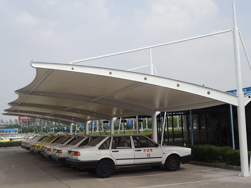
Different shapes involve varying design difficulty and material consumption, leading to significant price differences. For example, the simplest "7-shaped" carport costs less, while large-span designs (up to 20–30 meters) have higher unit prices due to more complex structures (no columns required).
3. Project Scale and Geographic Location
Project scale: Larger areas generally result in lower unit prices. For instance, small residential carports (15–30㎡) may cost between 500–1500 RMB/㎡, while medium-to-large projects benefit from spreading fixed costs like transport and installation, reducing the unit price.
Geographic location: The location of the construction site affects transport and labor costs. Remote areas or first-tier cities typically have higher logistics and labor expenses.
Geology and climate: Difficult terrain (e.g., slopes) increases foundation costs. Coastal and northern regions also require wind-resistant, corrosion-proof, and snow-load-resistant designs, which affect cost.
4. Additional Features
Adding lighting systems, drainage systems, smart charging piles, photovoltaic modules, or smart parking management systems can increase total costs by 10%–30%.
Summary
The cost of a membrane structure carport is mainly determined by membrane material grade, shape complexity, and area. PVC is economical, PVDF is durable, and PTFE is high-end. Understanding these factors helps you budget accurately and choose the right solution.
If you have any needs for membrane structure carports, feel free to contact us: 136 000 65322 (whatsapp) or mail to canobbio@canobbio.com.cn.
To learn more about membrane structure carports, please visit: https://www.cantensile.com/car-parking-shade_c42.
In tensile membrane structure engineering, the three most mainstream membrane materials are PTFE, PVC, and ETFE.
In simple terms:
* PTFE is the high‑performance "permanent building material"
* PVC is the cost‑effective "economic choice"
* ETFE is the ultra‑light "transparent soft glass"
Feature
PTFE (Polytetrafluoroethylene)
PVC (Polyvinyl Chloride)
ETFE (Ethylene Tetrafluoroethylene)
Structure & Material
Coated fabric: glass fiber base fabric coated with PTFE
Coated fabric: polyester fiber base fabric coated with PVC
Homogeneous material: no base fabric, made directly from ETFE resin
Light Transmission
Medium to high (10%–50%); diffused light, no glare
Low (10%–35%)
Very high (>95%) – "soft glass", adjustable
Self Cleaning & Service Life
Best: >30 years; non stick surface, rain cleaned
Fair: 10–15 years; prone to aging and dirt accumulation
Excellent: 20–35 years; smooth surface resists dirt
Mechanical & Installation
High strength but stiff, poor foldability, high fabrication precision required
Good flexibility, easy to fold and process, but lower strength and prone to creep
High tensile strength, elongation >400%, weight only 1% of glass
Typical Applications
Large permanent buildings (stadiums, airports)
Temporary or semi permanent structures (canopies, exhibition halls, small architectural features)
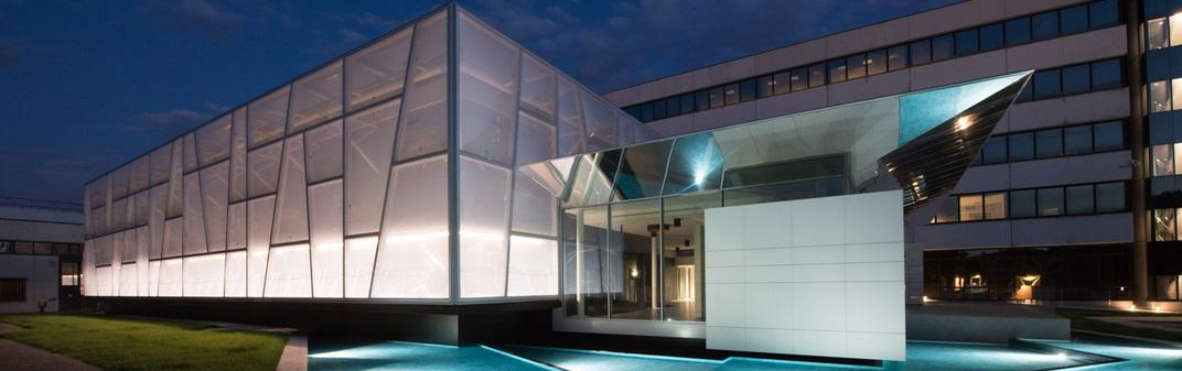
Landmark / viewing buildings (Water Cube, botanical gardens, atriums)
Approximate Price
60~120$/sqm
20~60$/sqm
100~200$/sqm
Detailed Differences
If you have a specific project (e.g., a parking canopy, stadium, or landscape feature) and a budget range, please you could contact us for more details: canobbio@canobbio.com.cn.
To put it simply, a membrane structure is a broad architectural category, while tensile membrane and spatial membrane are subsets or common terms based on different classification criteria. The relationship is one of inclusion, not equality.
Here is a detailed explanation.
A membrane structure is a building system consisting of high-strength flexible membrane materials (such as PTFE, PVC, or ETFE) and a supporting structure (steel frames, cables, or air pressure). The membrane forms a spatial shape through its own tension or internal air pressure, enabling it to withstand external loads (wind, snow, self-weight, etc.).
*Core Principle: Utilizes the material's tensile strength (not bending or compression strength). The membrane is stretched tight like a drumhead, creating stiffness to bear loads.
Three Main Types (based on structural mechanics):
1. Tensile Membrane Structure: Shaped by applying pretension to the membrane using steel cables and boundary supports.
2. Frame-Supported Membrane Structure: The membrane is draped over a rigid steel frame (arches, space frames), relying on the frame for shape.
3. Pneumatic (Air-Inflated) Membrane Structure: Shaped by internal air pressure (two subtypes: air-supported and air-inflated).
A tensile membrane is the most classic and expressive type of membrane structure. It's the common name for tensile membrane structures.
*Characteristics: The shape is maintained entirely by three-dimensional equilibrium tension between the membrane, steel cables, and rigid boundaries (ground, beams, columns). There are no internal support frames (no poles pushing up from inside).
*Typical Examples: The famous Munich Olympic Park roof, canopies around Beijing's "Bird's Nest" stadium, large landscape tents, gas station canopies.
*Intuitive Understanding: Like an inverted umbrella being pushed up by the wind from below – the membrane is the canopy, the cables are the ribs, but both work together to bear the load.
The term "spatial membrane" does not have a strict, unified engineering definition. Its meaning varies by context:
*Common Meaning 1 (3D Curved Shape): It emphasizes that the membrane creates a non-planar, doubly curved shape (e.g., saddle form, dome). Almost all tensile membranes and some frame-supported membranes are "spatial membrane structures," distinguishing them from flat membranes (like a simple awning).
*Common Meaning 2 (Analysis Method): In structural design software, "spatial membrane" sometimes refers to a membrane element analyzed using spatial finite element methods (considering 3D deformation).
*Common Meaning 3 (Trade Jargon): Some vendors call a frame-supported membrane with a curved shape (e.g., a park canopy with an arched steel frame) a "spatial membrane" to differentiate it from the more expensive "tensile membrane."
Key Point: In strict academic classification, "spatial membrane" is not an independent type. When people use this term, they usually mean either a "tensile membrane" (because of its strong spatial feel) or a "frame-supported membrane structure."
|
Aspect |
Membrane Structure
(Broad Category) |
Tensile Membrane
(Sub-type) |
Spatial Membrane
(Vague Term) |
|
Relationship |
The general term |
A specific type of membrane structure |
Not a standard type; often refers to tensile or curved frame-supported membranes |
|
Load Bearing |
Tension, frame compression, or air pressure |
Pure tension (no internal frame) |
Either tension or frame compression |
|
Internal Supports |
Possible (e.g., poles, frames) |
None (touches ground only at boundaries) |
Possible (if referring to frame-supported) |
|
Form |
Can be flat or spatial |
Must be a 3D double-curved surface (otherwise cannot be tensioned) |
Emphasizes a spatial curved shape |
|
Cost |
Frame-supported: cheaper; Tensile: more expensive |
Higher (complex form-finding, cables, connections) |
If meaning tensile → expensive;If meaning frame-supported → cheaper |
|
Typical Example |
|
|
Small carports, corridor roofs (with arch frames) |
One-Sentence Summary
*Membrane Structure = The parent (big family).
*Tensile Membrane = The talented child (most beautiful, technically core, relies purely on stretching).
*Spatial Membrane = The neighbor's nickname (not formal, often refers to a cheaper version that looks like a tensile membrane but has a frame, or simply any 3D membrane).
If any membrane structure project, please mail to canobbio@canobbio.com.cn.
1. Long life span: normally the suppliers provide 10-15 years warranty, but life span is over 30 years;
2. Fireproofing, High transmittance, Light weight;
3. Strong self cleaning ability: Because of its strong self cleaning ability, the PTFE tensile structure will become whiter after explosing to the sun.
please find below video comparasion of one PTFE tensile structure shooting in April and July, 2020, you can find it becomes whiter and more pretty over time.
PTFE Building Membrane Roof System Installation of Cable-membrane Structure in Foshan Home Furnishing Expo City
I. Project Overview
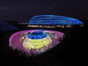
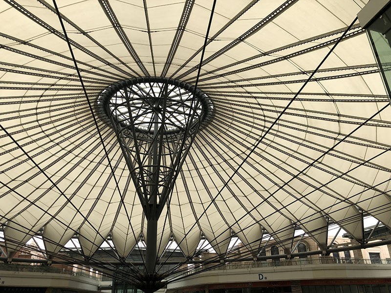
Foshan International Home Furnishing Expo City is located in Foshan City, Guangdong Province, which is the biggest international home furnishing saloon and hypermarket in Pearl River Delta at present. Four 9-layer large saloons with 1.80 million m2 respectively form into cross-shaped atrium, including roof day lighting and round umbrella roof. Atrium round umbrella roof is cable-membrane structure with diameter of 89m; 32 groups of V-shaped membrane form into suspension cable umbrella with diameter of 89m, the unilateral area of each piece of V-shaped membrane is about 370㎡, and the total area is 11840㎡. For the cross-shaped corridor, the combining roof between glass day lighting roof and membrane structure is supported by steel structure bearing, the entire covering area is 24,800 m2, and the membrane occupied 1/3. This project is located in Guangdong province with abundant sunshine and hot climate; through the calculation, the single face of each V-shaped membrane is up to 900m2, the length is up to 57m; finally, American Saint-Gobain SF-I PTFE membrane is adopted.
Figure II-5-1 “Cross-shaped” Atrium Roof of Foshan International Home Furnishing Expo City
The deepening design and construction of the steel structure, membrane structure and glass day lighting roof in this project as well as the cable system hoisting, tension and other works are completed by Guangzhou Canobbio Asiatex Construction Technology Co., Ltd, and this project is completed in September, 2012.
II. Structural System
The atrium round umbrella roof of this project is radiation double-layer cable system, which is generally set with tension inner ring; one end of the anchor for the double-layer cable is attached to the inner ring, and the other end of anchor is attached to the compression outer ring around. The diameter of this structure is 88m and the rise of the roof is about 25m. The major structure is composed of truss torus, inner ring fly column and double cable system up and down, and the surface is wave form covering with membrane materials. The cross section of truss torus is an inverted triangle with width and height of 6m, the upper-layer cable system is divided into upper ridge cable and upper valley cable; there are 32 upper ridge cables, 32 upper valley cables and 32 for lower-layer cable system.
As the anchorage point of the lower oblique cable, the lower node of the fly column is steel casting; the whole fly column weights about 250t, and the uppermost 15m-diameter top cap is composed of day lighting glass.
Figure II-5-2 Axonometric Drawing of Atrium Radiation Double Cable System


Figure II-5-3 Fly Column Node
![1E%%LYL4D_NUY]AZ6I@GERV](file://C:/Users/RodLaw/AppData/Local/Temp/msohtmlclip1/01/clip_image010.jpg)
Figure II-5-4 Profile Map
III. Technical Measures
Pre-stressed suspension cable structure is adopted for this project, and the structural construction has the following features through analysis and judgment:
= 1 \* GB2 \* MERGEFORMAT ⑴ Before tension-shaping of the structure, the suspension cable structure has smaller rigidity and poorer stability, and measures guaranteeing the stable structure are required to be taken during the construction.
= 2 \* GB2 \* MERGEFORMAT ⑵ The distance between the structure and the ground is about 60m and there are constructed and existed structures around, thus, large slings and tools as well as all-round scaffolds are not applicable to the construction.
= 3 \* GB2 \* MERGEFORMAT ⑶ The central inner pull ring steel structure weights 92t, cast steel joint weights 25t, inhaul cable weights 133t and the total weight is 250t. It is top-heavy structure, when the lifting point is below the umbrella-shape structure, it is extremely easy for the upper pull ring to overturn, thus, reliable measures must be taken to prevent and correct.
= 4 \* GB2 \* MERGEFORMAT ⑷ All lifting points are getting together to one point and the synchronization precision must be controlled strictly to make sure of effectiveness and safety of lifting steel strand and top cap during hoisting.
= 5 \* GB2 \* MERGEFORMAT ⑸ Construction simulation analysis is required to be conducted on the whole process of the construction to make the safety of the structure at every moment.
= 6 \* GB2 \* MERGEFORMAT ⑹ The monitoring of the whole process is required to be conducted on the construction and comparison between the real-time monitoring data and computable data to make sure of safety during the hoisting process.
= 7 \* GB2 \* MERGEFORMAT ⑺ Various adverse factors and emergency situation must be considered as adverse working condition to conduct the calculation; carry out the force analysis according to the most unfavorable condition to select hoisting equipment, designed hoisting and tension machines.
3.2 Construction Scheme
3.2.1 Process Flow of On-site Construction
The overall construction sequence of Foshan (International) Home Furnishing Expo City Suspension Cable is: after the assembly and qualified inspection of outer ring steel structure and fly column, connect all pull rings with the fly column, then hoist the 16 upper ridge cables (avoid the position of prominent buildings) with lifting jack; when it is hoisted to the certain height, install the upper ridge and valley cable, then the lower cable 1 and 2; next, adjust the upper ridge and valley cables; finally, the tension lower cable is completed with formed structural tension. The installation of 192 side cables is conducted after the completion of the tension. See Figure II-5-5 for detailed installation process flow.
SHAPE \* MERGEFORMAT
|
Steel structure ring beam and fly column are assembled and pass the inspection. |
|
Manufacturing of pre-stressed steel cables factory |
|
Transport to the site |
|
Install the fixed end of the inhaul cable |
|
Simulation calculation of construction |
|
Hoist the fly column |
|
Monitoring of fly column position point |
|
Install the adjusting end of upper ridge cable, upper valley cable and lower inhaul cable |
|
Simulation calculation of construction |
|
Adjust the upper and lower cable to make the fly column at the central position
|
|
Carry out the tension on the lower cable by three levels
|
|
Stress and deformation monitoring |
|
Install 192 side cables |

Figure II-5-5 Installation Process Flow
3.2.2 Cable system hoisting and installation
Step 1: After the outer ring steel structure and fly column are assembled and pass the inspection, conduct the pre-stress inhaul cable construction.


Figure II-5-6 Assembly Completion of Steel Structure
Step 2: Erection of operation platform


Figure II-5-7 Erection of Operation Platform
Step 3: Install the fixed end of ridge cable
Step 4: Install the fixed end of valley cable


Figure II-5-8 Install the Fixed End of Ridge Cable Figure II-5-9 Install the Fixed End of Valley Cable
Step 5: Install the fixed end of stable cable
Step 6: Install the fixed end of oblique cable


Figure II-5-10 Install the Fixed End of Stable Cable Figure II-5-11 Install the Fixed End of Oblique Cable
Step 7: Synchronous hoisting of 16 ridge cable and tooling cable


Figure II-5-12 Hoisting of Ridge Cable and Tooling Cable
Step 8: Hoist the fly column off the ground to 9m


Figure II-5-13 Hoist the Fly Column off the Ground to 9m
Step 9: Hoist the fly column off the ground to 14m


Figure II-5-14 Hoist the Fly Column off the Ground to 14m
Step 10: Install the adjusting end of the valley cable


Figure II-5-15 Install the Adjusting End of the Valley Cable
Step 11: Hoist the fly column off the ground to 22m and install the upper ridge cable


Figure II-5-16 Install the Upper Ridge Cable
Step 12: Transform the hoisting of the tooling to the oblique cable


Figure II-5-17 Transform the Hoisting of the Tooling to the Oblique Cable
Step 13: Loosen the adjusting sleeves of the ridge and valley cable
Step 14: Hoist the fly column to 28m


Figure II-5-18 Hoist the Fly Column to 28m
Step 15: Hoist the fly column off the ground to 34m


Figure II-5-19 Hoist the Fly Column to 34m
Step 16: Hoist the fly column to 40m


Figure II-5-20 Hoist the Fly Column to 40m
Step 17: Hoist the fly column to 46m and install the oblique cable


Figure II-5-21 Hoist the Fly Column to 46m
3.2.3 Tension scheme of structure
Step 1: Adjust ridge cable and valley cable
After the lifting installation is located, adjust the initial state of the structure; at first, pre-tighten the upper ridge cable and valley cable to make sure that the fly column is at the central position of the structure. Then, loosen the cable rope. The adjusting method of the upper cable: the central position of the fly column is changed through adjusting the length of the upper ridge cable and valley cable, the theoretical length of the upper ridge cable is 30,876 mm and that of upper valley cable is 36,130mm; adjustment is conducted according to the installation error of the on-site steel structure.


Figure II-5-22 Cable Force Analysis
Step 2: Oblique cable tension
Divide 32 oblique cables into 3 levels of tension, level 1 is to 30% of the design value, level 2 is to 70% and level 3 is to 100%.
In each level tension, divide 32 oblique cables into 8 batches of tension, i.e., 4 in each batch of tension.

Figure II-5-23 Oblique Cable Numbering
The tension sequence of level 1: 1→ 2→3→4→5→6→7→8
The tension sequence of level 2: 8→7→6→5→4→3→2→1
Midas, a large general software finite element analysis is adopted for tension position and the tensioning force of simulation analysis is as shown in Table II-5-1.
Step 3: After the tension is completed, conduct fine tuning on specific inhaul cable according to the data of construction monitoring.
Table II-5-1 Tensioning Position and Force

Since large lifting appliance and all-around scaffold cannot be adopted for construction, the construction process of inclined lifting radial cable is adopted. During lifting, the lifting of the lower cable is the most difficult to control; the structure barycenter is above the lifting point and there is no constrained point for the inner pull ring at the horizontal direction. It is potential that there may be lateral displacement at the structure. Therefore, selective analysis is required during the lifting of the lower cable.
1. Precision control of lifting the upper cable
During lifting the upper cable, there will be no structure instability since the lower anchor point of the upper cable is arranged at the circular ring (of which diameter is 15m) on the top of the inner pull ring; however, if there is a lifting point lifting too fast or too slow during the lifting, it will affect the lifting force of self-axis and adjacent axis, resulting in either rapid increase of lifting force or loose situation at a certain lifting point. Thus, it is required to conduct unfavorable condition analysis on each lifting state to determine the indicator of lifting precision control.
Table II-5-2 Cable Force Changes during Lifting the Upper Cable
|
ground clearance/m |
Maximum cable force of uniform lifting/kN |
Maximum cable force after the failure of a certain lifting point |
A certain lifting point is faster than other points (mm) /maximum cable force (kN) |
|
0 |
185 |
The cable force of the group increases, and the maximum is 221 |
100/601 |
|
9 |
245 |
The cable force of the group increases, and the maximum is 300 |
50/483 |
|
14 |
279 |
The cable force of the group increases, and the maximum is 341 |
50/532 |
|
22.2 |
390 |
The cable force of the group increases, and the maximum is 470 |
50/670 |
|
22.2 |
390 |
The cable force of the group increases, and the maximum is 470 |
25/590 |
From the table, it can been seen that in order to make sure that the cable force of single lifting point will not increase too much and make sure of safety during lifting, when lifting the upper cable and the internal pull ring is lifted 15m from the ground, it is required to control the lifting precision to 50mm; during the ground clearance of the internal pull ring is within 15~22.2m, the lifting precision is controlled to 50mm to make sure of sufficient safety coefficient for the lifting system.
2. Precision control during lifting the lower cable
During lifting the lower cable, although in which the upper cable has been installed with hinge pin, there will be no constraint formed to the top of the inner pull ring since the upper cable is under the loose state; therefore, it is very possible that the whole fly column may tumble laterally during lifting the lower cable. For this, cable rope is set at the top of the fly column as horizontal constraint. However, after the top elevation of the fly column exceeds the external pressure ring, it is required to loose the cable rope from time to time during the lifting in case that it is under too much stress. In addition, the lower anchor points of the lower cable are all at the same point, that is to say, during lifting the lower cable, it is exerting the lifting force on the same point. If the synchronous lifting cannot be achieved, there will be a certain lifting point of which lifting force increase quickly or the fly column cannot be lifted. Thus, analysis must be conducted on each lifting state and determine the reasonable lifting precision index under the premise of safe lifting structure.
Synchronous control program is adopted for this system and the computer is used to control the lifting tension of the oil pump and the jack, effectively controlling the cylinder stroke of the jack. Upper and lower limiting stoppers and staying sensor are set on the jack respectively, allowing the displacement of each lifting point controlled. To avoid cumulative error during lifting, make a marker on the lifting steel strand every 50cm in advance; in this way, the marker error of the steel strand can be checked at any time, and correct each steel strand by using computer operating system. At the same time, the principle of double control with force and displacement is adopted, 6 control cabinets are controlled by one computer controlling platform, each control cabinet controls the solenoid valves of 2 or 4 oil pumps, and it is controlled by the computer whether the solenoid valve provides oil with jack or not. Staying sensor is set on the jack, transmitting the displacement data to the computer timely, and the computer is used to control the synchronism and total cylinder quantity between jacks. The oil pressure signal is transmitted to the computer timely through the oil pressure sensor set on the jack; set safety oil pressure in the program, and when the actual oil pressure reaches the safety oil pressure, the program will command the solenoid valve not to offer oil to make sure that the pressure of the jack will not exceed a certain limiting value.
Lifting process is divided into upper cable lifting and lower cable lifting, and there will be no structure instability in upper cable lifting, therefore, it mainly control the precision of the synchronous lifting. During the lower cable lifting, it considers about not only the tumble possibly occurred in the structure, but also the synchronous controlling precision of the lifting.
Limited by the on-site construction environment, there are high-level existing buildings around the internal pull ring, therefore, only 16 inhaul cables can be lifted by 32 axes at the same time, and it is controlled in accordance with given requirements for synchronous precision.
After the upper cable is positioned, transfer the lifting jack and lifting tooling to the corresponding position to lift the lower cable. At this time, the upper cable is always under the loose state; therefore, 4 cable ropes are arranged at the upper end of the fly column as the horizontal constraint of the fly column; the other end of the cable rope is fixed at the external ring beam, when the upper end of the fly column is lower than the external ring beam (i.e., the ground clearance of the fly column is 33m), the cable rope will be tightened uninterruptedly along with the lifting of the lower cable, and the tension of the cable rope will not increase during the lifting.


a Fly column is just off the ground b Fly column is 9m from the ground


c Fly column is 14m from the ground d Fly column is 22m from the ground and the upper cable is positioned
Figure II-5-24 Upper Cable Lifting


a Lifting tooling of the lower cable b Fly column is 28m from the ground


c Fly column is 33m from the ground d Fly column is 46m from the ground and the lower cable is positioned
Figure II-5-25 Lower Cable Lifting
However, after the top elevation of the fly column exceeds the external ring beam, the internal force of the cable rope will increase with the lifting of the lower cable, which causes adverse effects on the safety of the cable rope; therefore, it is required to stop the lifting at certain height of the lifting according to calculation, loosen the cable rope and then conduct the lifting, so repeatedly until the lower cable lifting is positioned.
3. Construction process monitoring
It is required to conduct on-site construction monitoring on the structure, guide the safe and précised implementation of the construction process and accumulate the data information of the pre-stressed engineering construction to make sure of the safety of the whole construction process in the project and investigate the change rule of the deformation and internal force of the structure during the construction. The main monitoring objects are the cable force of the lifting cable and the lateral deformation of the fly column during the lifting, therefore, there are 2 sets of total station arranged at the perpendicular direction of the structure to offer the whole-process construction monitoring during lifting, making sure that the skewness of the fly column is controlled within 5° during the whole construction process. Figure II-5-26 is the results comparison between cable force monitoring of inhaul cable at typical position and simulation analysis by adopting Midas, large general finite element analysis software. Through the cable force monitoring, it is found that during the lifting, the measured value of cable force for inhaul cable is a little bit higher than the calculated value while the large deflection rate is within 5%, which shows that the simulation analysis method during lifting is reliable and may be used to guide the on-site construction.


Figure II-5-26 Cable Force Monitoring of Inhaul Cable During Lifting the Upper Cable
Safe and fast safety net is adopted for the installation of membrane in this project, which saves the costs of scaffolds largely.

Figure II-5-27 Construction Personnel are Installing Membrane on the Construction Net
Hoist the membrane to the position to be installed and stretch the membrane along the direction of the installation according to the drawing to make sure of correct installation direction of the membrane.
The top membrane side is connected with the top ring; fixture is installed at the hard pressure side of the membrane; tighten the membrane to the installation position with chain hoist; drill at the surface of the membrane with electric portable drill after alignment; install the aluminum platen and tighten the pull rod.

Figure II-5-28 Top Membrane Installation
Adjust the length of the ridge cable and valley cable to comply with the drawings, making the whole system under stress; after this step is completed, the whole membrane surface shall be smooth without wrinkle, simultaneously, and the flange at four angels may be adjusted to achieve the requirement of smooth for membrane surface.
I. Economic and Technical Indexes
The following advanced technologies have been adopted in this project construction:
= 1 \* GB2 \* MERGEFORMAT ⑴ Computer synchronous control program is adopted for the control of 16 sets of lifting equipment to lift the same point of the structure;
= 2 \* GB2 \* MERGEFORMAT ⑵ The lifting point is set at the lower point of the structure, lifting the structure through setting pre-bias for the structure combining with the ring rotation lifting method to make sure of stability of the fly column during the lifting;
= 3 \* GB2 \* MERGEFORMAT ⑶ Safe and fast safety net is adopted for the installation of membrane structure, which saves the costs of scaffolds largely.
II. Project Photos

Figure II-5-29 Panorama of Round Umbrella Roofing for Atrium

Figure II-5-30 Interior Scene

Figure II-5-30 Partial Interior Scene

Construction Plan of Atrium PTFE Membrane for Foshan Home Furnishing Expo City
As per the FSA (Fabric Structures Association), a division of the Industrial Fabrics Association International, a tension structure or tensile structure is a structure that is characterized by a tensioning of the fabric or pliable material system (typically with wire or cable) to provide the critical structural support to the structure.
Fabric tensioned structures are typically used as a lightweight roof, protective cover, shelter, skylight, advertisement and/or identification for stadiums, arenas, shopping malls, amphitheaters, bandshell, stage cover, tents, and shade structures for airport and transportation depots.
Tension structures utilize technical fabric roof membranes, a combination of catenary cables and clamping systems, and a minimal amount of framing to create proportionally lightweight structures capable of spanning great distances. Tensile membranes are available in exterior grade vinyl and woven fabrics and teflon coated fiberglass. These tensioned membrane structure fabrics carry from seven to twenty years warranties.


 Online service
 +8613600065322
 canobbio@canobbio.com.cn
 +8613600065322